Building the Voron 0.1
The seed for the idea to build a 3D printer was already planted in my head when I bought the Ender-3 at the beginning of the year. It may have been there since I saw a Rep-Rap the best part of a decade ago. And Eric, from whom I had bought the Ender 3, had just finished building his replacement, a Voron 2.4, which he had bootstrapped using the Ender 3.
It was a YouTube video fron CNC Kitchen that caused the seed to sprout - when he described his reasons for the build, I realised that the potential for a tiny and fast printer matched my own goals. The larger Voron 2.4 was too big and too expensive for me to consider, but the tiny Voron 0.1 would be the perfect prototyping machine for me.
The Voron project is the best self-built printer design of the moment, an open source schematic that allows anyone to build a top-of-the-line printer from parts.
Eric dismissed the Voron 0.1 as a toy - understandably from the perspective of a larger Voron owner, the tiny build plate seems inadequate, but if I look at the history of things I’ve printed, it’s rare for them to be large enough to require a bigger area.
I vaccilated over the idea for over a month before clicking buy on the FormBot components kit on AliExpress. Although the Voron BOM contains sourcing information for each component, I had little patience for that and instead opted to buy the FormBot kit that contained all the non printed parts necessary for the build.
The Frame
The kit arrived before I had even had a chance to order the ABS necessary for the colours I wanted to build with. While I waited for that, I put together the rails. The nut trays that I had printed were slightly off dimensions, despite my printer being perfectly calibrated, and it took some wrestling before I could get each rail to screw to the aluminium extrusion. In retrospect I should have reprinted the nut trays with some size adjustments.
By the time the prints for the bed carrier were done, I was ready to mount them on the rails, and the first problem struck. One of the rails was crunchy and jerky, and certainly not smooth enough to bury within the bowels of the machine. Much has been written about low quality Chinese linear rails, and it seemed that my bet on the FormBot kit had not paid off. In order to not be blocked, I swapped the bearings with the ones from the X-axis, and ordered some more cheap bearings off AliExpress.
I had been very meticulous with measuring as I went, but even still, the tolerances on the Voron design are very small, and I struggled to wrestle the last screw into the last blind nut within the bed assembly. Even before tramming the rails, my squareness seemed to be slightly off. I loosened all the joints and was able to get it together. It seems that most of the joints need to be eased together and only tightened when the entire assembly is complete.
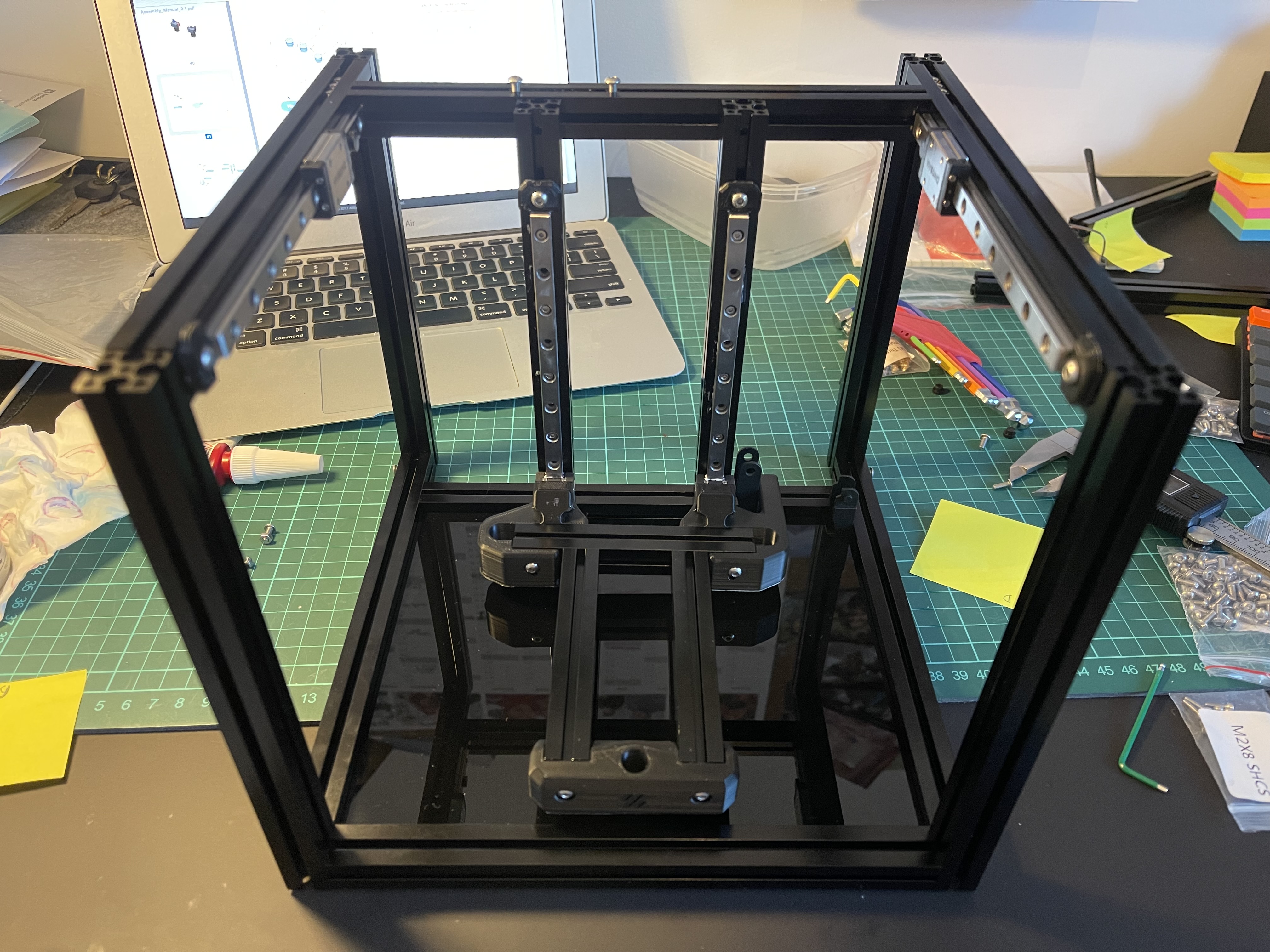
After the Z axis is complete, the rest of the frame falls together pretty easily. It was straightforward to build out, and even more straightforward the second time, after I was forced to disassemble the whole thing to add some nuts that were on the wrong beam. The Voron team take an extremely minimal approach to the documentation, and I had ordered the beams from a few pages before incorrectly.
I appreciate the effort the Voron team have gone to to make the documentation for the build so complete - the quality is incredibly high - but the minimalism is an aesthetic that detracts from the experience of the build, and there are myriad warnings throughout the instructions about what can go wrong. I wonder if there is a way to highlight these problematic components more explicitly to avoid the confusion. With a community project like this, you could even track the specific components that tripped people up and have statistics on the most problematic areas.
Regardless, a few hours later and I had a frame before me, with diagonals that measured as straight.
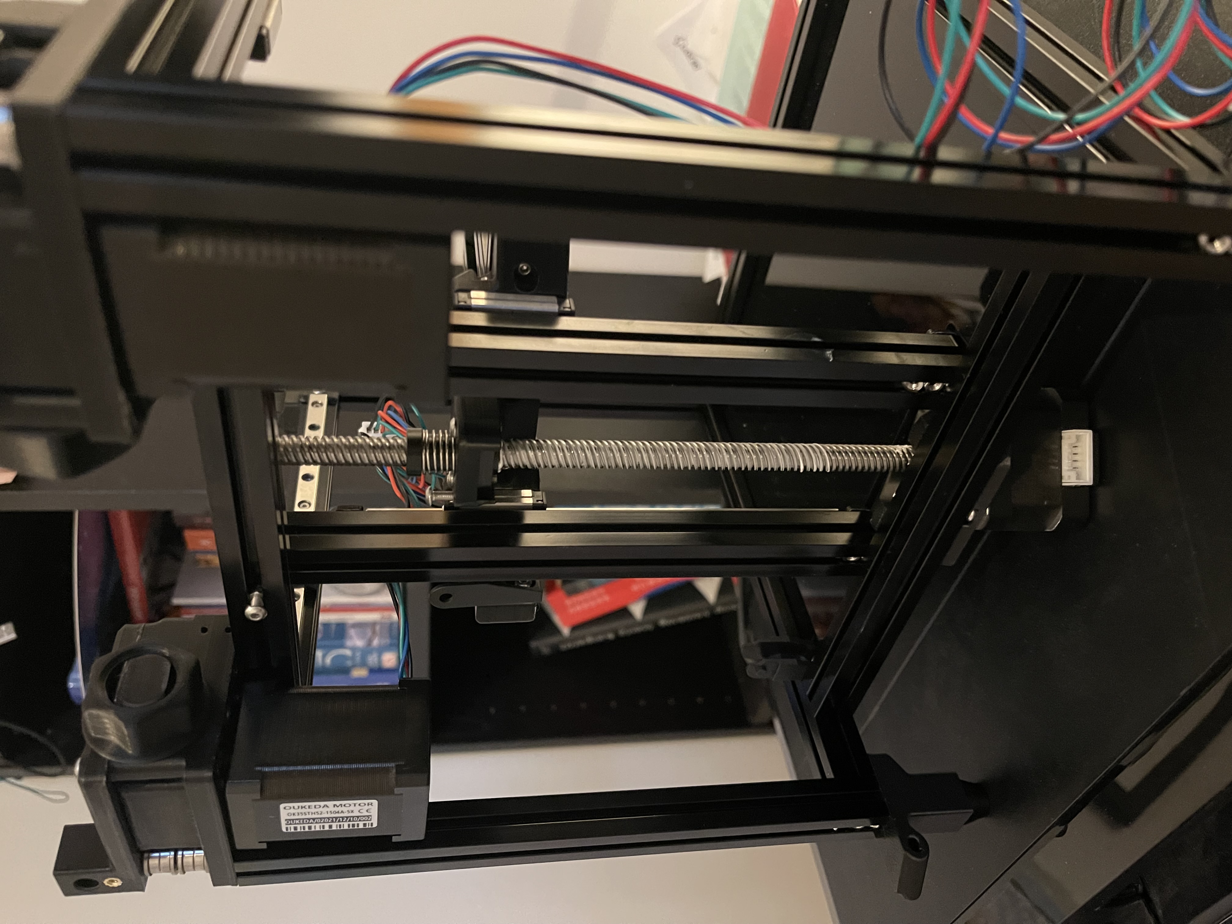
The Motors, the Gantry, the Bed
After the frame is assembled, you add the 2 beefy stepper motors at the back that will drive the X and Y axes. Voron uses CoreXY mechanics which are really counter-intuitive and hard to picture - instead of a motor per axis, each motor drives a looped drive chain that differentially drives both axes. To move forward, both motors move in opposing directions. It's hard to get your head around until you play with it, but the major advantage is that it takes all of the weight of the axial movement and puts it away from any moving part, meaning the moving weight (and thus momentum) is far less. This sort of genius really highlights the beauty of this design.
This part of the build has a lot of 3D printed parts with melted-in brass threads, and I had to reprint some of these after my soldering iron overly melted the plastic.
The next part of the build is the gantry, and I had thought I would have to wait for my new linear bearings to arrive, but after thoroughly drenching the rail in grease, it seemed to move acceptably, so I thought I would continue the build and worst case, reassemble the X-axis later.
The gantry pieces didn't seem to be designed to the same level as the rest of the build so far, the tolerances seemed off, and some adjustment was required. It was also here that I stripped my first bolt of the build, and had some stressful disassembly to do.
I straightened the gantry, then added the belts, but after tightening the belts the gantry alignment was off. I had to do a fair amount of disassembly before it was possible to get it true.
I wish the Voron design included more adjustability and features to tune, rather than relying on such tight tolerances. As it is, the only real recourse you have when something isn't square is a bit of brute force, or reassembly. The design assumes very tight tolerances with all of the pieces, including the printed pieces, and, although the design allegedly accounts for it, the shrinkage of ABS pieces means you are often fighting slightly undersized pieces.
Once the gantry was completed, it was time to finish the print bed. I vaccilated over how best to wire the thermal fuse inline with the heated bed, before opting to use a junction box ziptied underneath. At this point the printer really started to look like it was coming together.
The Hotend, Wiring
The instructions suggest assembling the hotend next, but after struggling to print a few of the pieces, due to some issues with the Ender 3, I had fallen behind the build, and therefore I decided to do some of the wiring first.
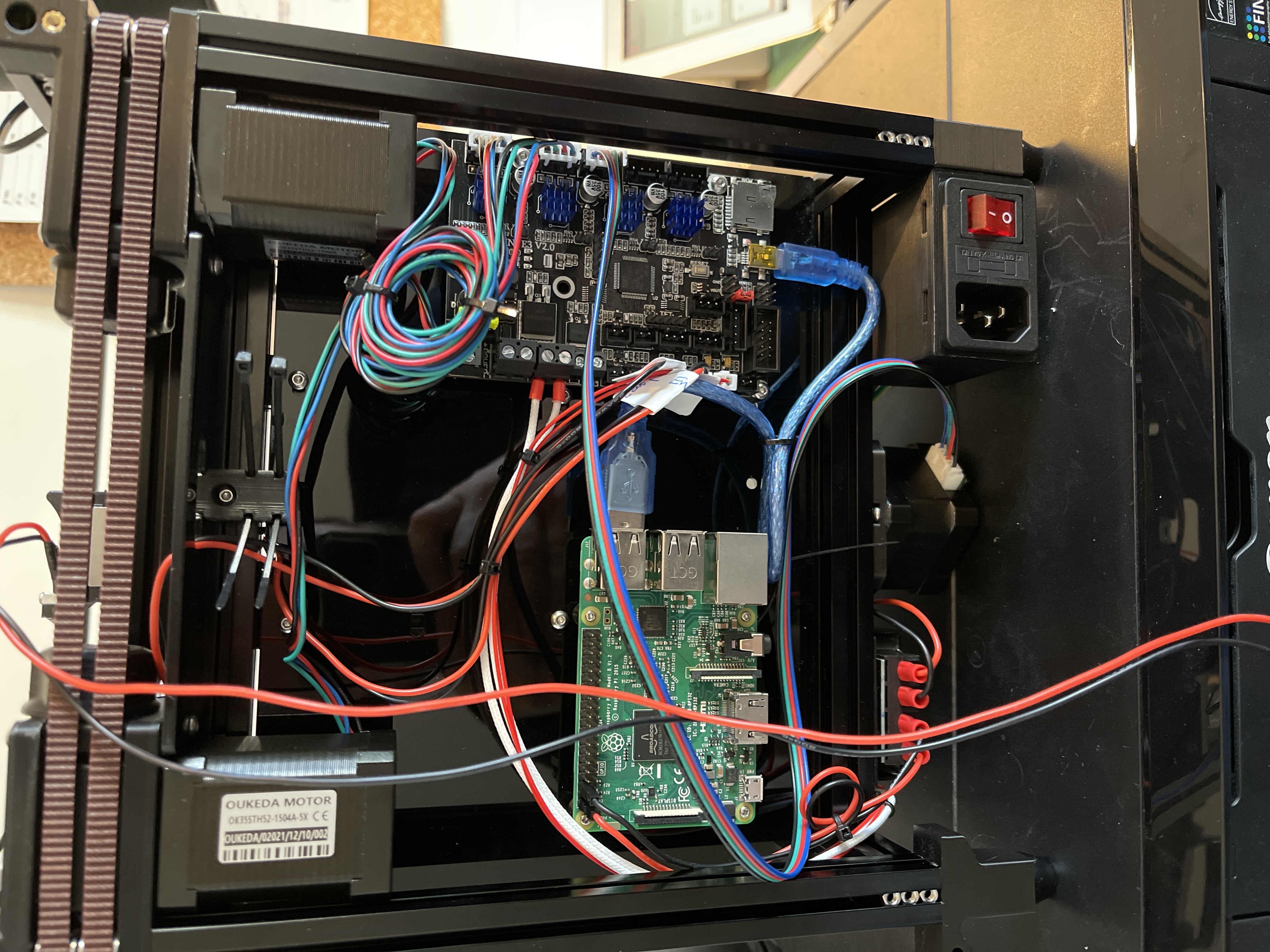
The Formbot kit comes with a full wiring harness which was really convenient, and saved a lot of work, but sadly the power cables to the control board were far too short, and I needed to splice in some additional cable.
I followed the instructions very literally, and almost immediately regretted it, as the components are very tight together and, there is little room for the USB cabling between the Raspberry Pi and the control board. I ended up moving the Pi later - it's far easier to have it right up against the side of the machine, which also give nicer access to the SD slot.
As the pieces completed, I attempted the hotend assembly. This was a pretty delicate procedure - the fan wiring needed some adjustment, and everything was very fiddly. The instructions become pretty vague with wiring at this point, and it took a fair bit of additional research to understand how everything fit together.
I had very few additional parts to print on the Ender 3, and was starting to get complacent, when one of the prints failed so badly that it required a full disassembly of the Ender 3 hotend to unclog the nozzle that had become embedded in a piece of plastic. It gave a nice opportunity to compare the designs of the hotends though.
Everything was coming together, I finished the wiring, although everything was very messy, and I hadn't sheathed the cables from the hotend.
First Startup
I started double checking everything before powering on - checking stepper motor wirings, double checking each connection. The stress of the build was getting to me - I wasn't even convinced the thing would power on, so it was a relief when I turned the machine on and didn't see any smoke.
I had installed the software, and was ready to start working through the configuration checklist.
As soon as I buzzed the z-axis, a loud static noise came from the machine. I wasn't sure if I had a bad stepper or a bad power supply, but after realising the stepper was getting really hot, and some advice from the discord channel, I enabled 'stealthchop' on the Z- axis configuration.
I should mention that until this point in the build, nobody mentioned the detail that would be required in the configuration files - having ordered a kit, I had no idea the exact model of thermistor or heated bed I had ordered. I made my best guesses, but choosing the appropriate current for the steppers gave me some stress.
The Z-axis was a cheap chinese model that came with the kit, and apparently it's common for these low quality motors to be noisy. Stealthchop is a setting that does some magic with pulse width modulation to quieten the motors, at the expense of a little torque, although considering this is a screw driven axis, I didn't think the loss of torque would be so important. I also lowered the current to try and reduce the heat that the motor was producing.
At this point in the instructions, all of the Voron printers are combined, and it's a bit of a mess to wade through the instructions to find the relevant steps. The detail drops precipitously as the instructions progress - there are no instructions on how to load the filament, and it became clear that I had an issue with my extruder.
I was forced to completely disassemble the hotend to workout why the filament wasn't feeding into the extruder. I suspected the gearing, but in fact, one of the holes through a printed part wasn't big enough - I had assumed there would be a little tolerance added here, but the hole was too small, and I had to enlarge it with a needle and an acetone soaked tissue.
I reassembled, then realised I had forgotton to add the PTFE tube back after my dissasemblement. After assembling it for the second time, it failed to extrude, and I realised, the PTFE tube hadn't mounted into the heatsink correctly.
I assembled the hotend for the third time, and crossed my fingers - a small thread of melted filament poked through the nozzle - it was working!
I continued through the checklist, and got to the first print. I clicked go, and watched as the printer came to life and printed out a small calibration cube. The printer was alive!
Calibration
The next steps are a series of test prints and adjustments to hone the configuration to the intricacies of the build. I went through these methodically, still not quite daring to believe that the printer was working correctly. And of course it wasn’t entirely. One of my blower fans wasn’t working, it appears I had a dud in my kit. This was very demoralizing as a replacement would take weeks to arrive. Thankfully, I could continue to print, albeit a little slower,
The final steps were to build the rest of the case, including the top hat, and get everything together for a video for the serial number on reddit. The last few prints were large pieces, and my struggling ender 3 messed up many attempts, including some of the worst nozzle clogging and bed adhesion problems of the whole build. In frustration I ended up printing the last couple of pieces on a raft, and was surprised how easy it made it.
The filament roll was almost done when I finally printed the last piece - apart from the extruder, all of the printer took a single roll of filament, including many failed parts,
Putting together the top hat was another exercise in frustration. During the process I ran out of M3x6 bolts and had to substitute M3x8 instead, but actually these fitted together nicer anyway.
I was finally there - I took a few videos of the printer printing the calibration cube and uploaded them to the Voron reddit page to wait for a serial number for the printer, which came a few days later - I have built V0.1549.
Thoughts
The Voron is a fantastic design. Building it was a stressful and difficult project, especially because of the minimal instructions, and lack of adjustability. But these are minor critiques of an otherwise incredible effort by a set of volunteers. For a free set of instructions, the quality is incredible, and the team deserve nothing but kudos for what they have done.
The Formbot kit was pretty much what I expected - some fairly low quality parts, but everything was there, including plenty of spare nuts and bolts, and a premade wiring haress (albeit with some adjustment required to make it work). I wouldn't have had the patience to source everything myself, so a kit was a must-have. I think all things considered, the Formbot one was fine - I would buy it again. If I were to buy it again though, I'd order some spare rails, and perhaps some alternate motors so as to have options during the build. Most of the components are fairly cheap individually, and the main problem is the lead time from China, so it doesn't hurt to order some spares when getting everything together.
The Voron team seem pretty against kits, and I’m sure having to deal with endless issues caused by chinesium parts can be a sisyphean task, but for a new builder, looking at the BOM and contemplating the amount of orders and shipping fees needed to purchase everything individually is daunting. I think that as long as you keep the mindset that a kit is a starting point, and replacements will be needed, then you will be happy.
This was my first time building such a complex piece of machinery from parts, and I enjoyed the process, although it definitely involved a fair amount of tearing my hair out and a steep learning curve.
It's amazing that we've got to the point, that with some bits and pieces ordered off the internet, and a set of free instructions, anyone can build a robot that can print precise 3D pieces out of melted plastic. It feels like the future.